A design isn't finished when it works on paper. It's finished when it's survived contact with reality: production floors, race weekends, and everything that goes wrong in between.
Automotive-focused mechanical engineer with hands-on experience across OEM production equipment and race-car component design, from diagnosing shop-floor failures to designing and validating hardware on a Formula SAE car.
Education
B.S. Mechanical Engineering, University of Alabama, Class of 2028
Program
Honors College · Automotive Minor · Accelerated STEM-to-MBA
Every one of these started as a real failure or an open question, then got designed, built, and proven under real conditions before I called it done.
HONDA
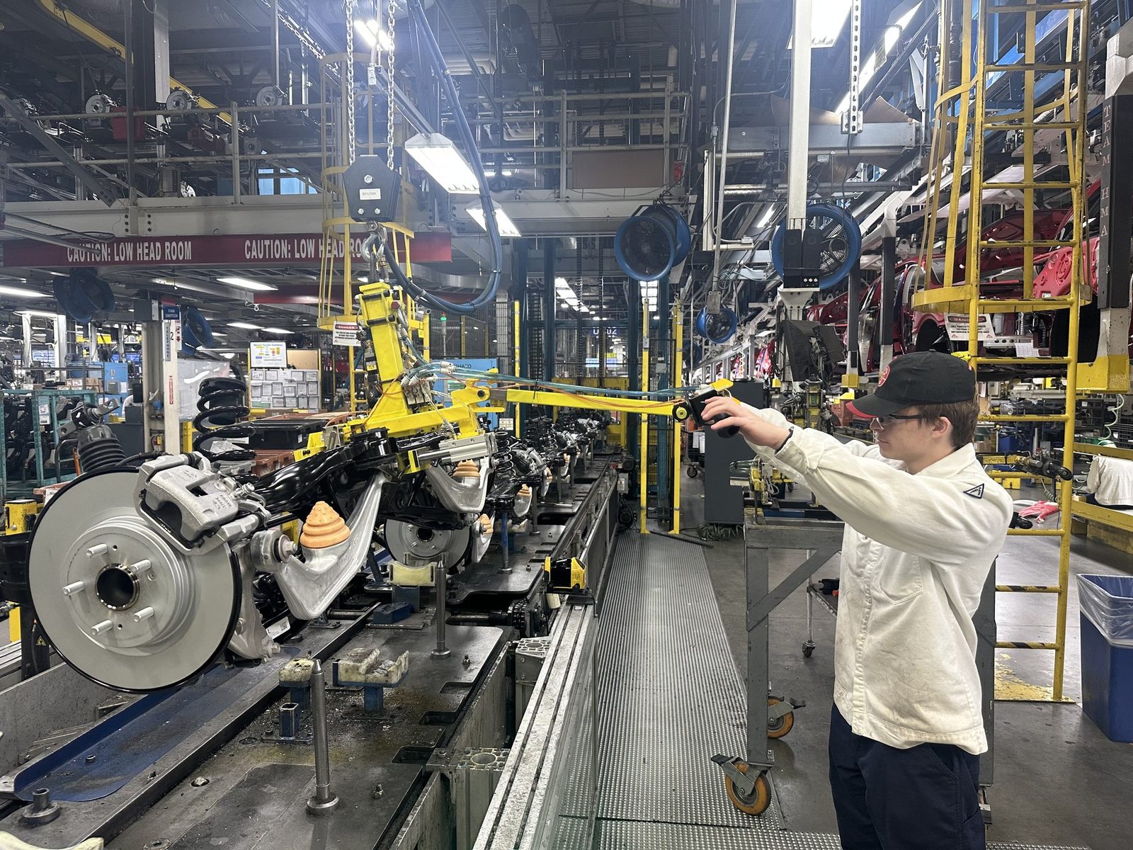
Rear Suspension Lift-Assist
Equipment Engineering Co-op, Honda Motors · Lincoln, AL · Fall 2024 – Spring 2025
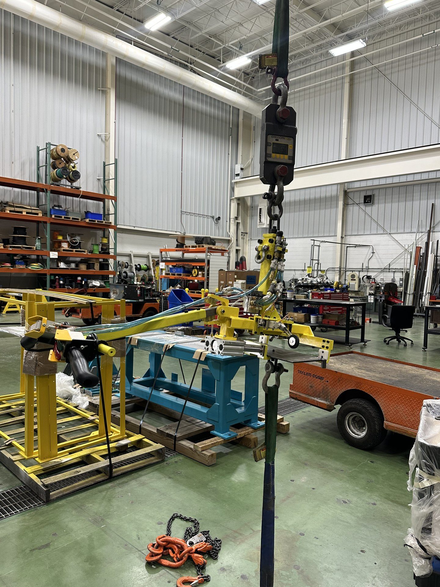
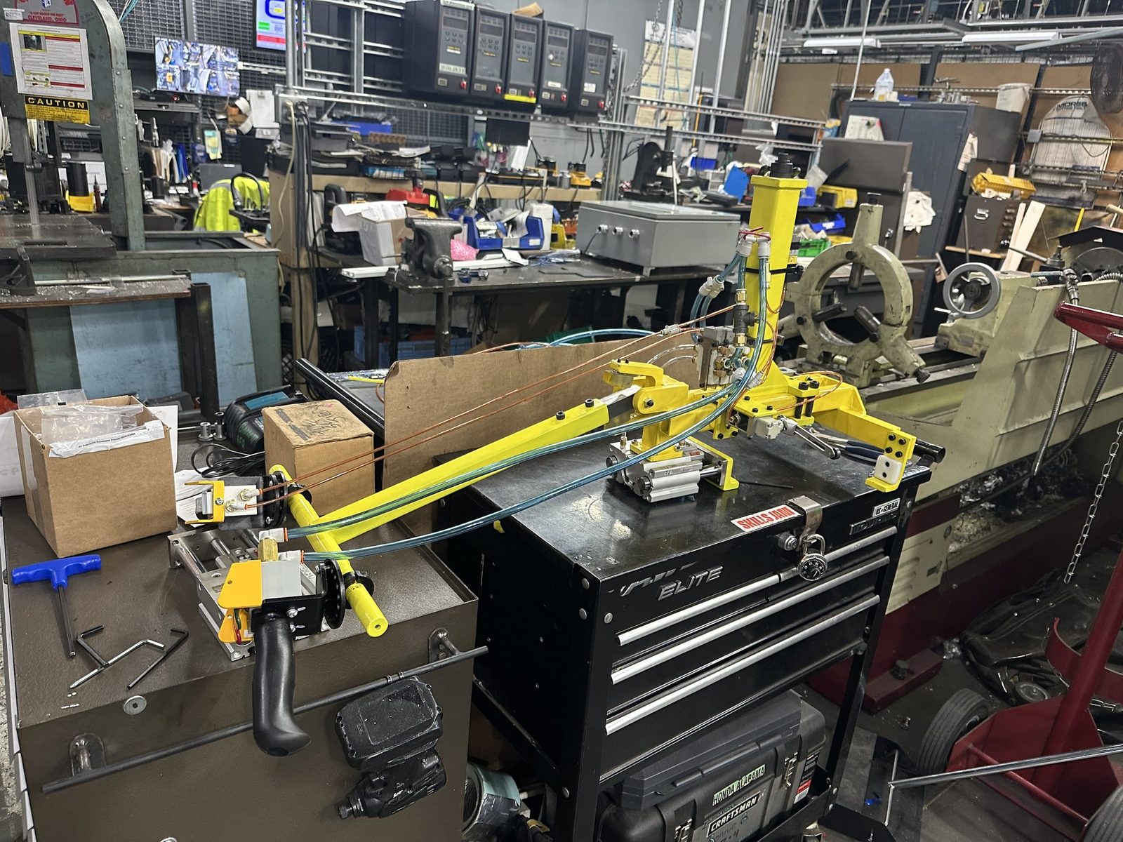
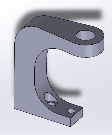
Originally scoped as a reinforcement fix for the failure-prone body of an aging lift-assist, the project grew into a full rebuild after repeated patch-fixes on the old unit caused frequent breakdowns and line downtime. Designed, cut, welded, and painted a new frame in-house, then rebuilt the pneumatic circuit (solenoid valves, controls, and tubing) around a single hub so the whole system is traceable at a glance. Replaced the old rigid contact point with a C-joint and rubber pads to cut the physical toll on associates, and simplified the connection down to the bottom cylinder.
Lift assist being pulled to a FOS of 1.7
DESIGN DEEP DIVE
From Patchwork to Rebuild
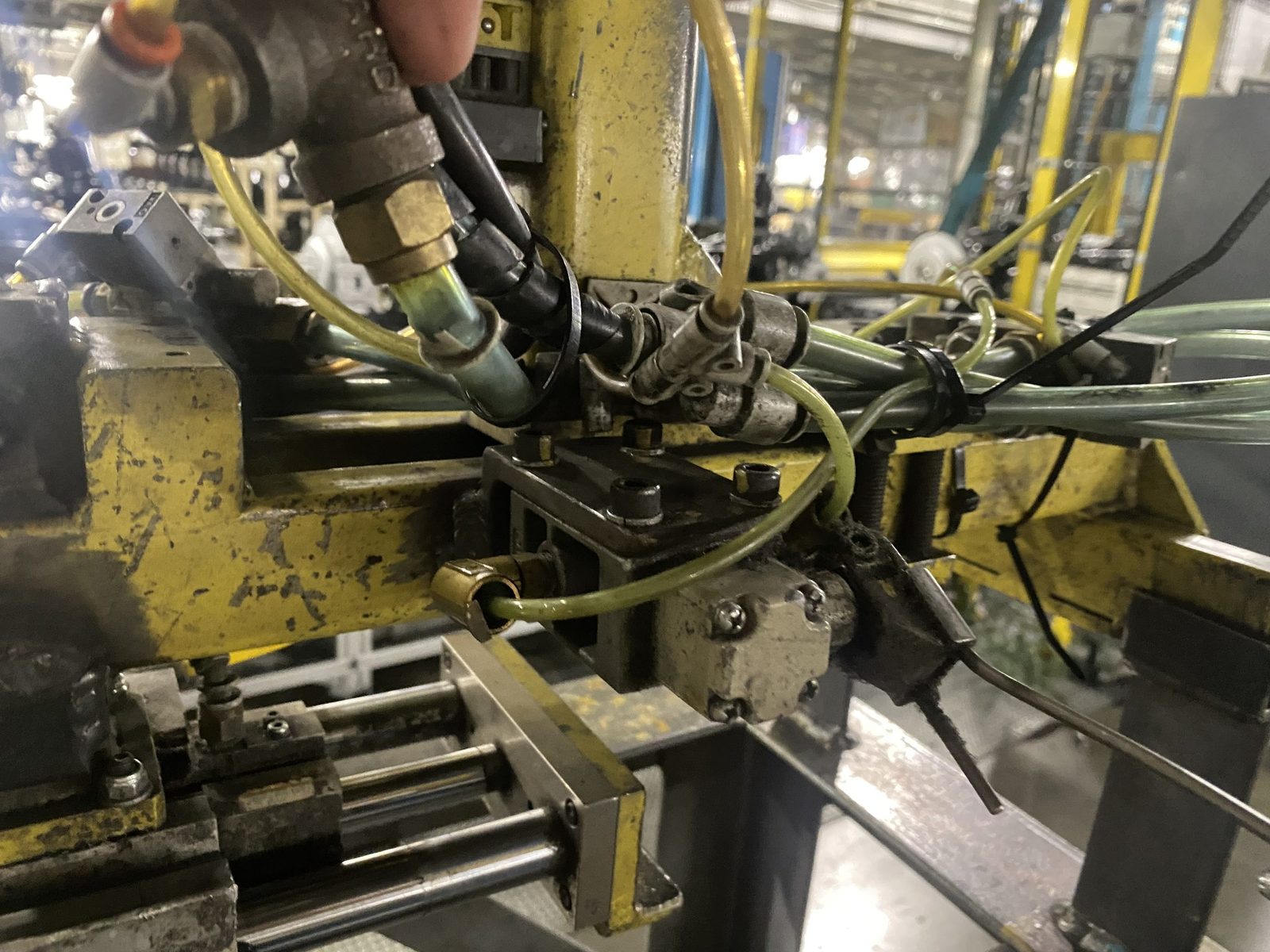
Original pneumatic layout
Quick repairs left the routing untraceable, extending diagnostic time with every failure.
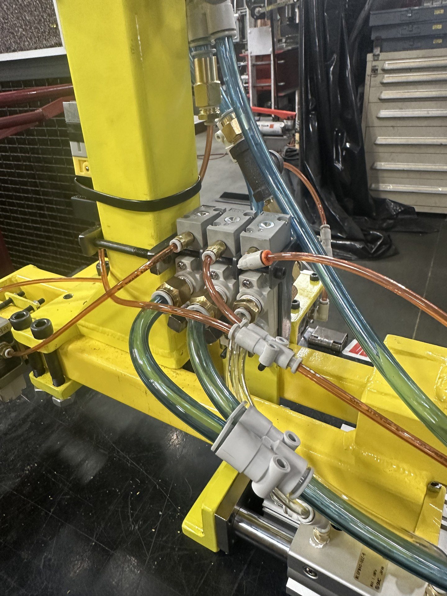
Updated centralized hub
All valves and tubing routed to a single serviceable point, cutting diagnostic time.
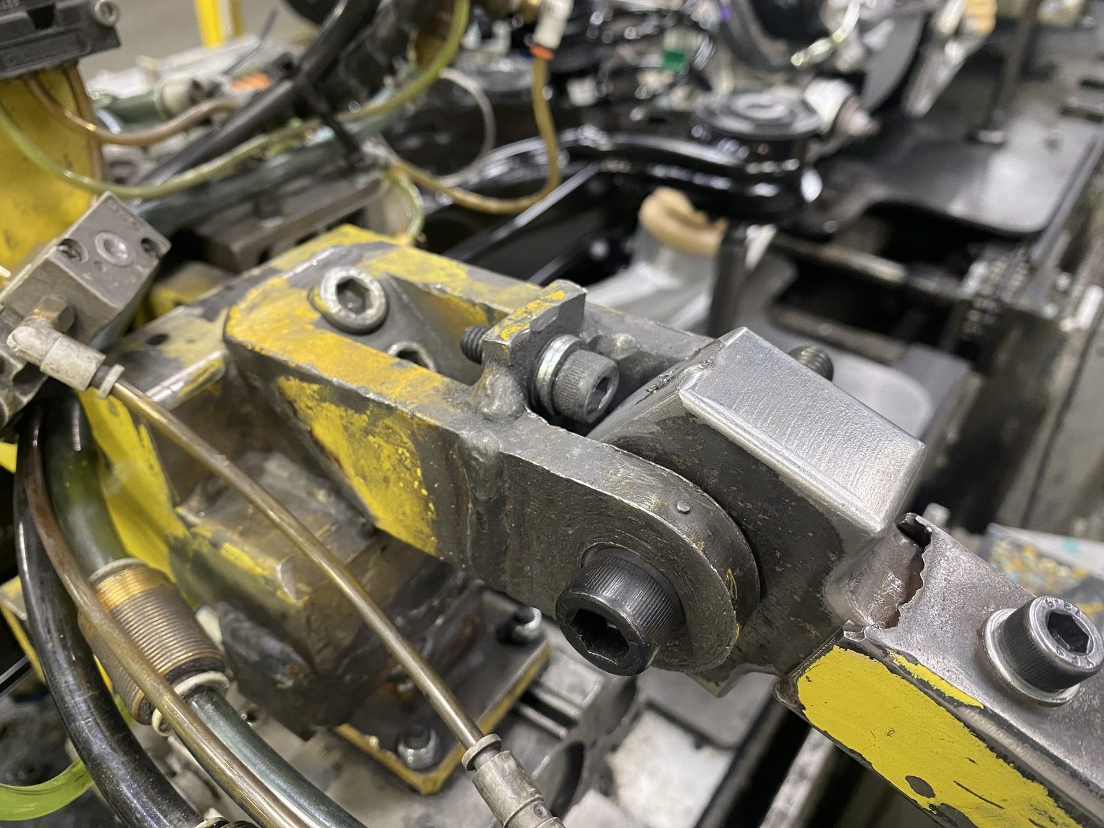
Original arm rotation limiter
Metal-to-metal contact accelerated wear on the mechanism and the associate, repeatedly cracking the limiter.
Updated rubber-padded limiter
A rubber-padded C-clamp absorbed impact loads previously transmitted into the structure and the user.
RESULT
In service over a year with zero unplanned downtime, only routine rubber pad replacement.
Validated via: stress tested to a factor of safety of 1.7
Key insight: fixing the root design instead of the failure points ended the maintenance cycle.
Equipment Engineering Co-op, Honda Motors · Lincoln, AL · Spring 2025
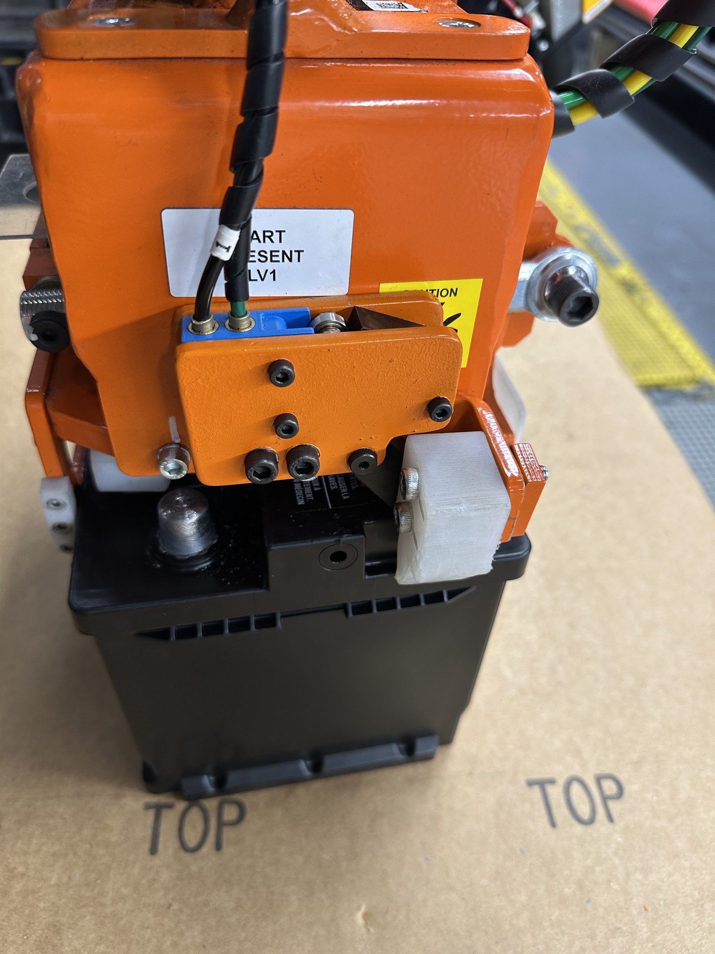
Designed, fabricated, and integrated part-presence switches into the battery lift-assist fixture to confirm proper grabber engagement before lift initiation. Resolved recurring failure modes present in the previous design, which was prone to frequent jamming, resulting in improved reliability, reduced downtime, and a more efficient assembly process.
THE PROBLEM
Diagnosing the Jam
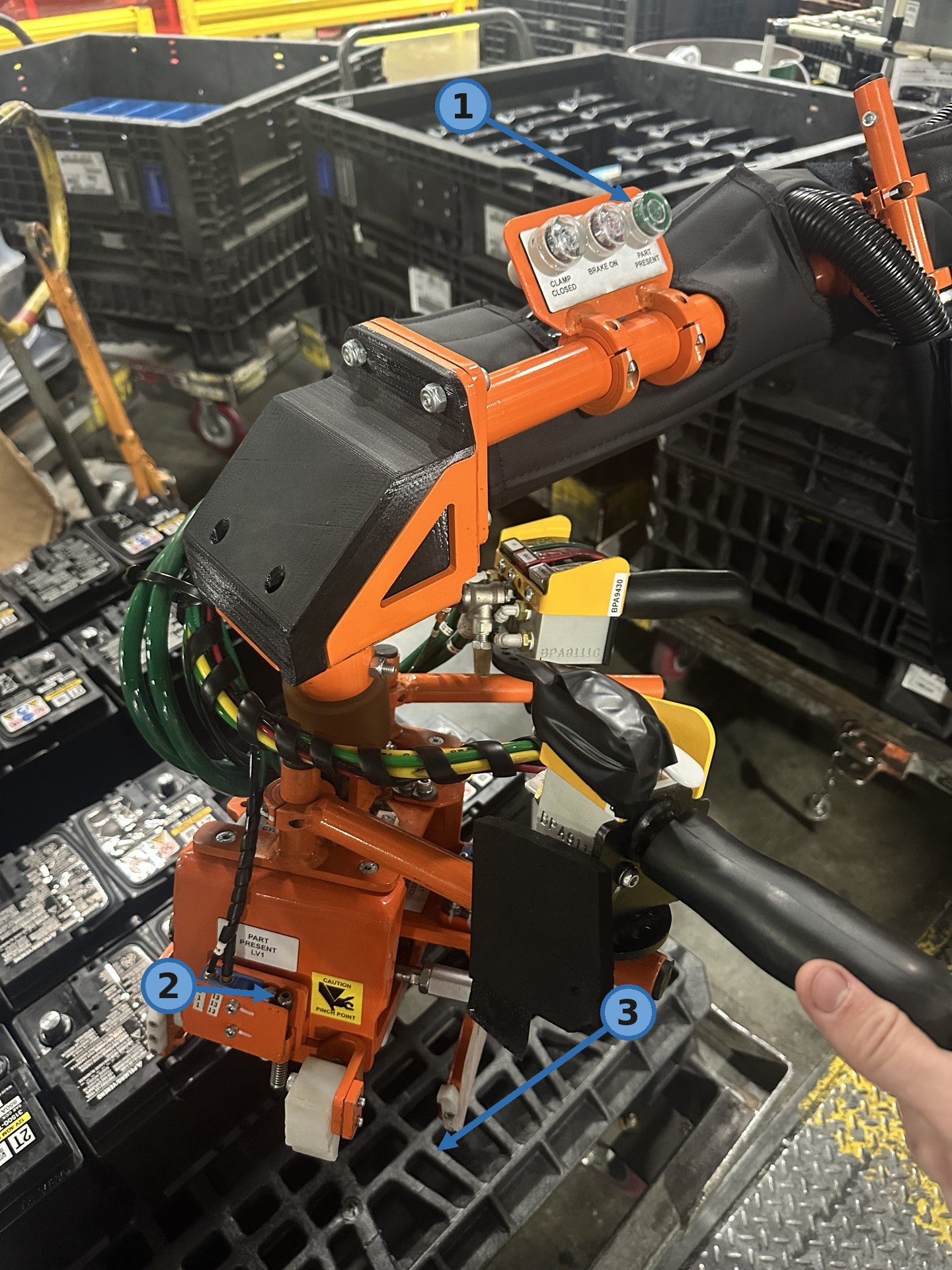
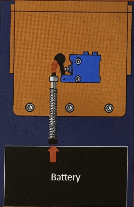
1Part-presence indicator: ON, the fixture reads a false positive.
2Pin jammed on sensor, the root cause: the original pin design binds under repeated cycling.
3No battery present, the actual, unsafe state the jammed pin was masking.
THE FIX
Old pin design
A linear pin had to seat into the sensor by hand, an alignment-sensitive interface prone to binding and jamming.
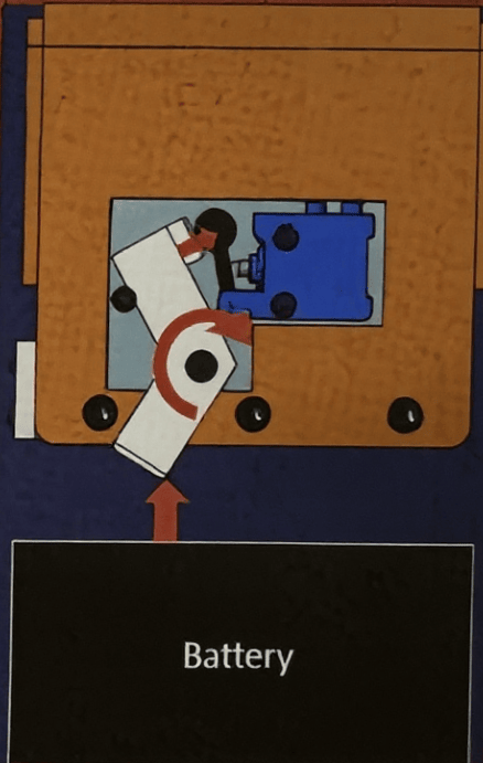
New switch design
A rotating lever engages the sensor directly, removing the pin-binding failure mode entirely.
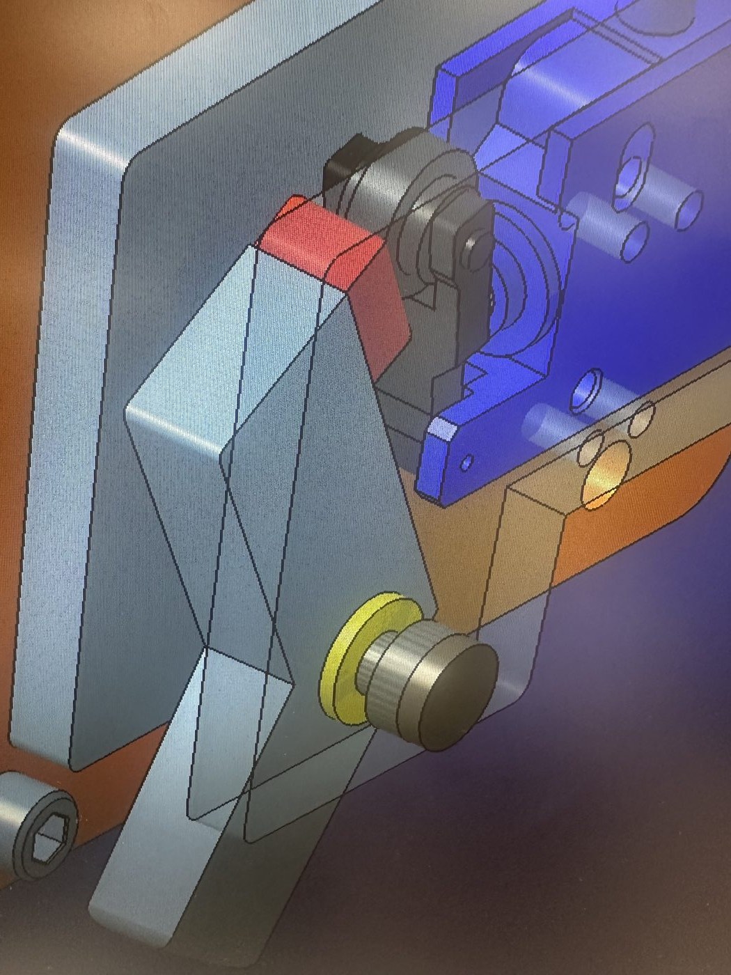
Full CAD assembly
The redesigned switch, actuator flag, and mounting bracket modeled in context on the lift-assist arm.
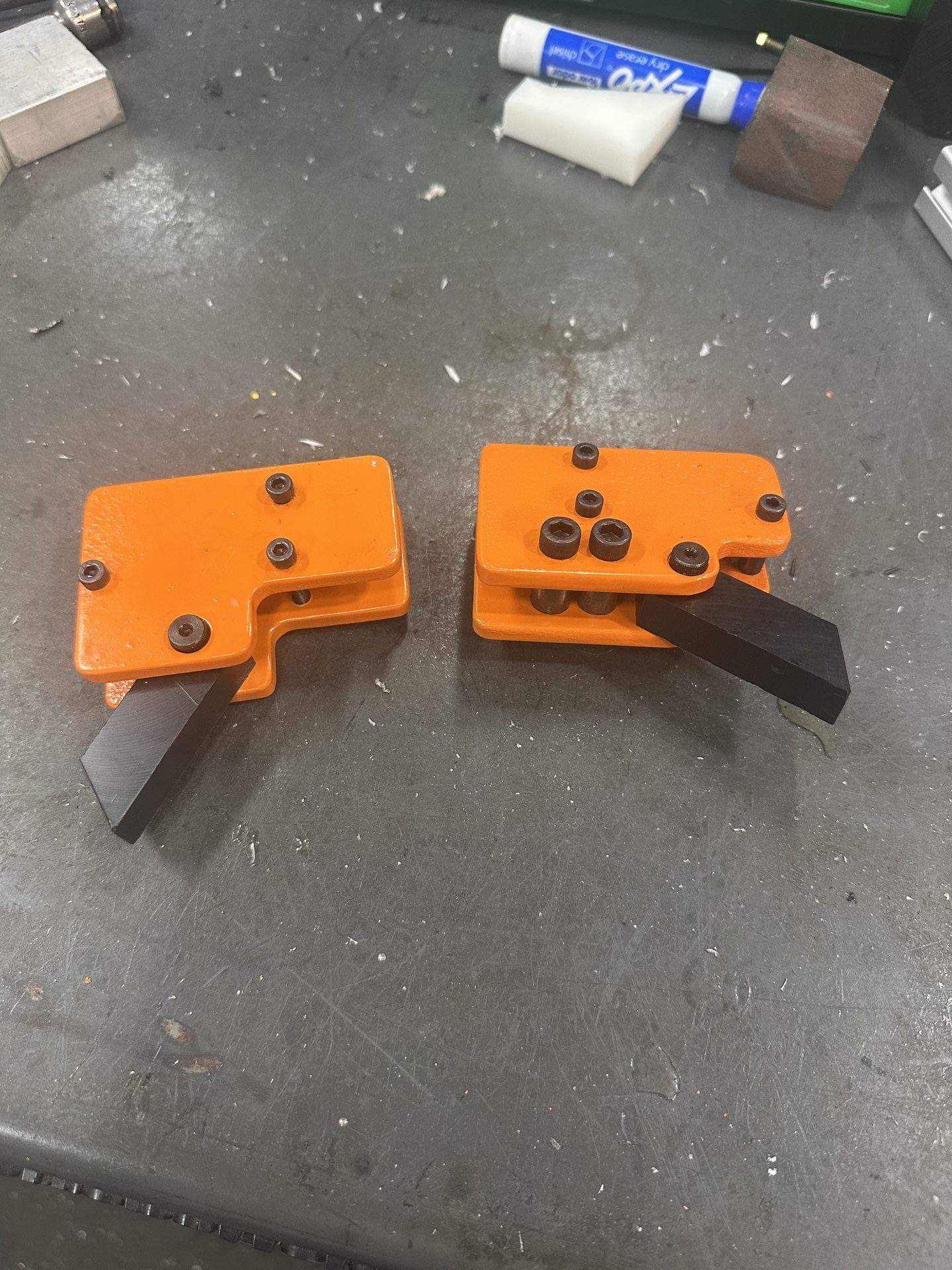
Final iterationSwitches implemented on the lift assist
RESULT
Fabricated the switch components in-house using Delrin for the actuator flags and 1/8-in. steel for the housing. Validated performance through between-shift installation and testing prior to full production implementation.
Validated via: line trials
Key insight: material selection took a couple of tries: metal was ruled out immediately, and even nylon proved too abrasive against the battery face before Delrin's lower friction made it the right fit.
Suspension Team Member, Crimson Racing – Formula SAE · Fall 2025
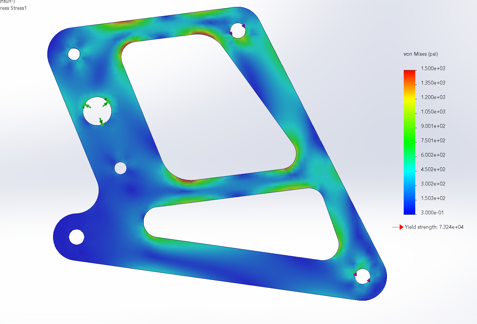
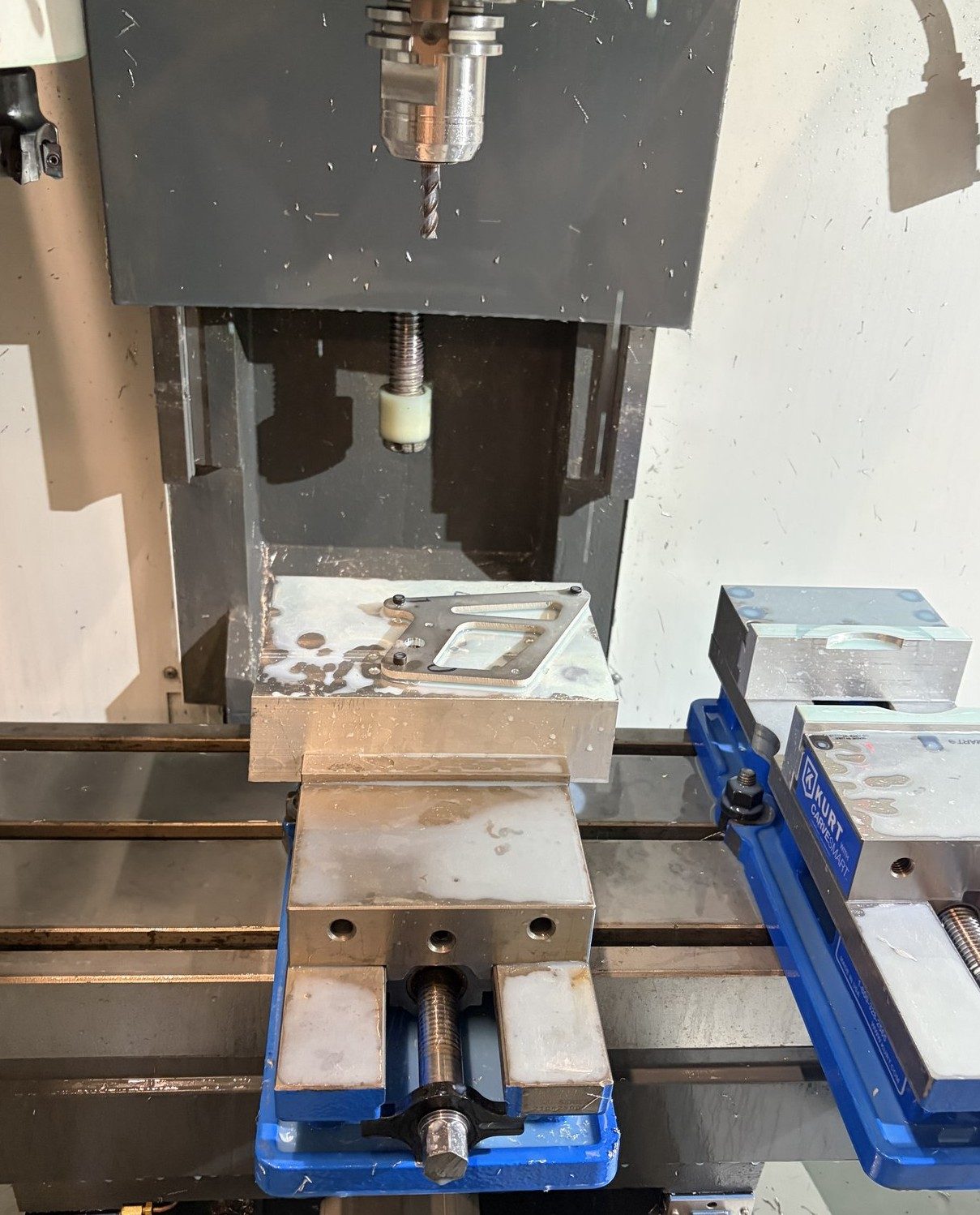
Designed a new rear bellcrank from the ground up, working within fixed attachment points for the pullrod, pushrod, and pivot. Modeled the geometry in SolidWorks, ran FEA against the known load case the part would see, and machined the final part from 7075-T6 aluminum, selected over steel to minimize mass while holding FOS comfortably above 1.6.
Final design FEA on von Mises scaleBellcranks fitted onto suspension assembly
Front and rear bellcranks post-waterjetMilling holes for push bearingsRear bellcranks installed on the car
RESULT
Held up across every drive day and competition run of the season with no failures or performance issues, validating the design under real cornering loads.
Validated via: FEA and on-car testing
Key insight: analysis gave confidence in the design, but a full season without failure was what actually proved it.
TOOLS & METHODS
SolidWorksFEACNC MachiningMilling
FORMULA SAE
Wheel Speed Sensor Validation
Suspension Team Member, Crimson Racing – Formula SAE · Spring 2026
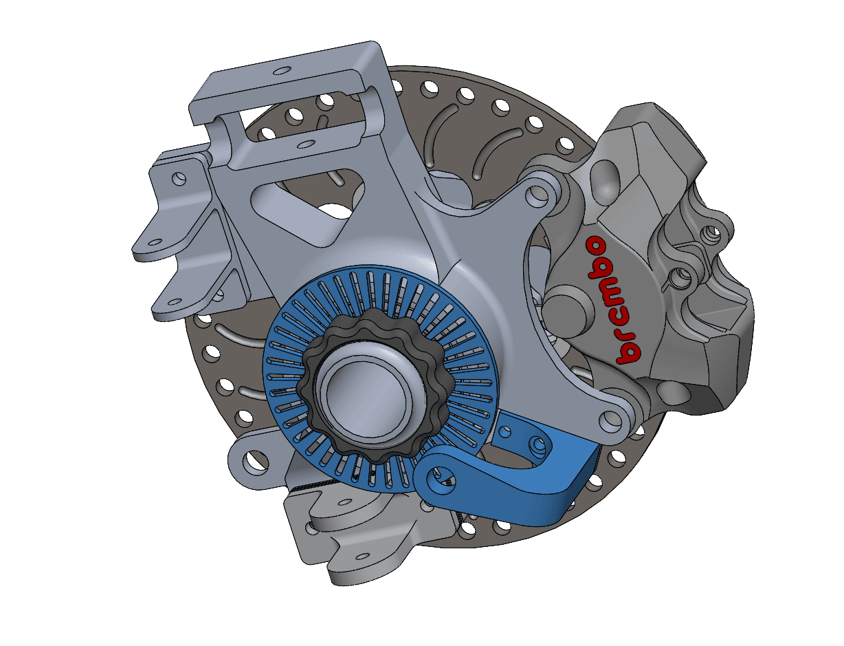
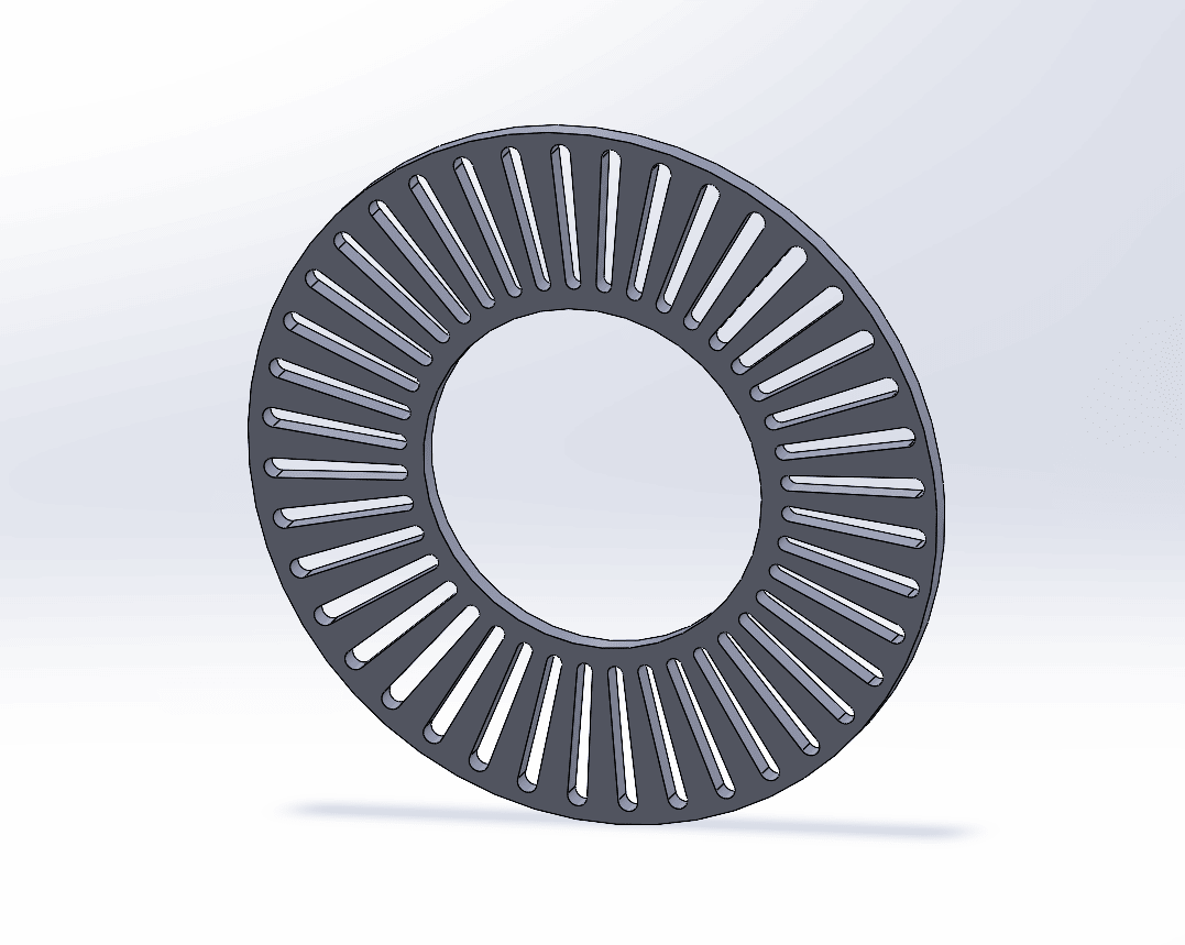
Designed a slotted tone ring and a mounting bracket to position a magnetic speed sensor at the wheel hub. As the tone ring rotates, the sensor detects each passing slot via magnetic reading, and the resulting pulse frequency correlates directly to rotation speed, and by extension, vehicle speed. Modeled the tone ring's slot geometry and spacing in SolidWorks, had it waterjet-cut, and mounted it at the hub to validate both the sensing method and the underlying frequency-to-speed calculation for shared use across the team's combustion and electric cars.
Wheel hub assembly with tone ring and sensor mount
RESULT
Validated a shared wheel-speed-sensing method, with the sensor, tone ring, and mounting geometry all designed in-house, for use across both the combustion and electric platforms.
Validated via: on-track data logging, comparing the logged speedometer to the wheel speed sensor results
Key insight: validating on the hub instead of the bench forced the design to work in real conditions, making it trustworthy enough to carry over to the electric car.